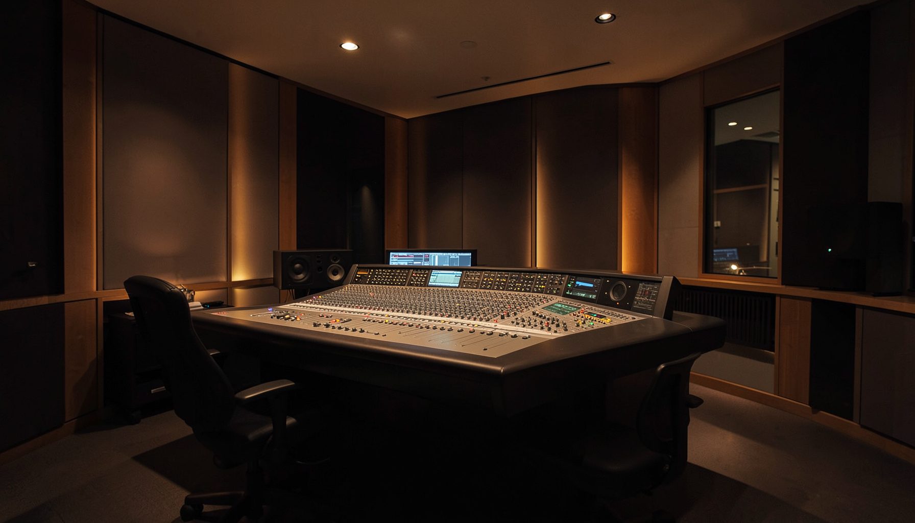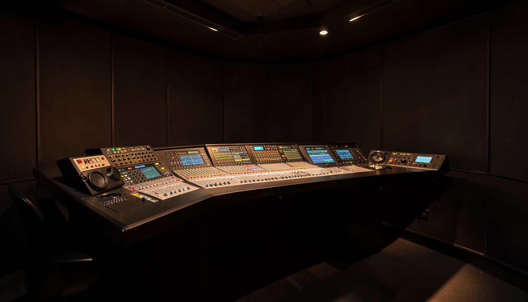
Using Power Core's Analog Outputs for Studio Loudspeaker Calibration
Accurate monitoring begins with a reliable signal path. In a Lawo radio facility, Power Core can provide the analogue outputs needed to feed nearfield monitors, control-room loudspeakers, headphones, or a dedicated metering chain. Calibration then becomes a repeatable engineering task rather than a subjective adjustment made from the presenter’s chair.
The process is especially valuable in networked studios, where several rooms may share sources, monitor feeds, and production resources. A consistent reference level helps operators make similar decisions in Sydney, Melbourne, Brisbane, or a regional station, even when the rooms have different acoustic dimensions and loudspeaker models.
Power Core’s flexibility also makes it possible to separate programme audio from monitoring control. The output used for loudspeaker alignment can be assigned deliberately, labelled clearly, and documented in the station’s configuration. This reduces the risk of calibrating through an unexpected gain stage or changing an operational output by mistake.
Calibration does not mean making every room sound identical. It means establishing a known acoustic reference, matching the left and right channels, checking low-frequency behaviour, and confirming that normal working levels remain comfortable. The result is a monitoring environment that supports dependable decisions during live radio, voice production, and post-production.
Prepare The Signal Path
Start by documenting the complete route from the Power Core processing engine to the loudspeakers. Identify the DSP or mixing source, the analogue output channels, patch points, monitor controller, amplifier inputs, and any active loudspeaker sensitivity controls. Bypass unnecessary processing, including automatic gain, loudness enhancement, and equalisation that is not part of the permanent room design.
Set Power Core output trims conservatively and confirm that left and right channels use the same nominal level. Balanced analogue connections are preferable for professional studio distances, particularly where equipment racks, computers, and lighting circuits could introduce interference. Check polarity and channel identification before sending test signals at a low level.
Use a calibrated sound-level meter at the main operator position. A measurement microphone connected to suitable analysis software can provide greater detail, but the instrument must be used consistently. Place it at seated ear height, midway between the loudspeakers, and avoid holding it close to the body, which can affect high-frequency readings.
Establish A Practical Reference
Pink noise is useful for broad system checks because it exercises the full audible spectrum, while a sine-wave tone helps identify routing faults and unexpected level changes. Begin with the monitor gain reduced, then raise the Power Core output or monitor controller gradually. Do not use the loudspeaker’s rear-panel sensitivity as the everyday volume control once the reference has been established.
Many broadcast facilities choose a reference around 79 to 83 dB SPL, measured with suitable weighting and response settings, depending on room size and operating practice. A compact voice booth may require a lower working level than a large production control room. The important point is that the selected reference is written down and applied consistently.
Australian stations should also consider occupational noise exposure. Safe Work Australia’s model guidance treats prolonged exposure to high sound levels as a workplace risk, while requirements are implemented through state and territory systems. A calibration session should therefore be brief, controlled, and followed by normal monitoring at a comfortable level rather than continuous high-level playback.
Match Channels And Room Response
Play the same broadband test signal through each main loudspeaker and adjust the system until the left and right readings are closely matched at the listening position. Listen for a stable centre image with speech and voice-over material. If the image pulls towards one side, check polarity, cable routing, input sensitivity, and the physical angle of the monitors before applying equalisation.
The room has a major influence below about 300 Hz. A corner-mounted subwoofer, reflective desk, or asymmetrical wall can create peaks and nulls that cannot be corrected reliably by changing Power Core’s output gain. Measure several positions around the operator area and make modest equalisation changes only after the loudspeaker placement and listening position have been reviewed.
For facilities with several rooms, a central visual display can make monitoring states easier to verify. A centralised VisTool dashboard can show selected sources, output trims, mute status, and room assignments, helping engineers spot an incorrect monitor path before it affects production.
| Calibration point | Recommended check | Practical result |
|---|---|---|
| Routing | Confirm source, output, polarity, and channel labels | No hidden or reversed signal path |
| Reference level | Record the chosen SPL and measurement method | Repeatable operator monitoring |
| Stereo balance | Compare left and right at the listening position | Stable centre image |
| Low frequencies | Measure several positions and inspect room modes | Fewer misleading bass decisions |
| Documentation | Save trims, test signals, and date of verification | Easier maintenance and handover |
Integrate The Workflow With Power Core
Once the loudspeakers are aligned, save the operational settings in a controlled configuration. Separate engineering access from everyday presenter access where possible. A host should be able to select a normal monitor source without accidentally changing the calibrated output trim or bypassing a protection limiter.
Power Core can support different destinations for control rooms, studios, edit suites, and external feeds. Label each analogue output according to its physical destination, not just its channel number. “Studio B left monitor” is more useful during a fault than “Output 14,” particularly when a Melbourne facility is being supported remotely from another city.
Keep calibration tones and test sources available, but restrict their access during live programming. A short test playlist can include pink noise, mono speech, phase checks, and music with controlled dynamics. This makes routine verification faster and avoids relying on a familiar commercial recording whose mastering may conceal a system fault.
Verify Speech And Real-World Operation
A technically matched pair can still be uncomfortable or misleading when used with real broadcasts. Check spoken-word material at the level operators use every day, then audition music, phone codecs, remote guests, and compressed feeds. Radio voices often expose midrange harshness or excessive sibilance more clearly than pink noise.
AutoMix and other dynamics tools can alter the apparent balance between sources, so calibration should be checked with representative processing states. Guidance on source-specific compression settings is useful when speech, music, and remote contributions share a studio workflow. The monitor path should reveal those changes without adding its own character.
Recheck the system after moving loudspeakers, replacing an amplifier, changing desk furniture, or updating routing logic. In Australia’s 230-volt, 50-hertz environment, power and equipment changes may occur during a broader studio upgrade, so analogue output levels should be verified after maintenance rather than assumed to remain unchanged.
A concise calibration record should list the Power Core configuration, analogue output trims, loudspeaker model, measurement position, reference SPL, date, and engineer. Store the record with the studio documentation and place a small reference mark on the monitor controller. The practical takeaway is simple: route a known signal through Power Core, measure at the operator position, match the system carefully, and preserve the settings so every shift starts from the same acoustic reference.