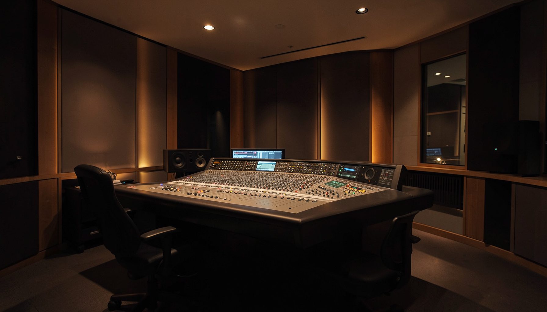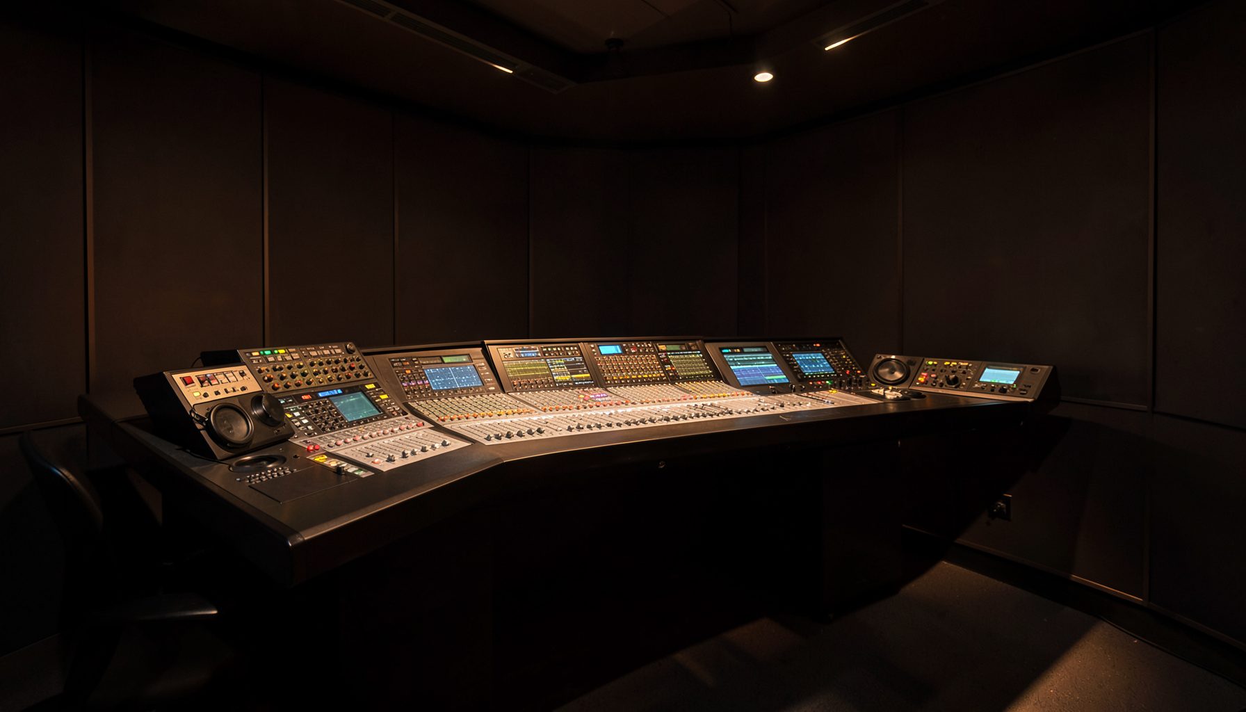
Ruby GPIO Pins for Physical Start Button Control
Many Australian radio studios prefer a physical start switch beside the microphone, especially during overnight automation and early breakfast shifts. It gives presenters a clear, tactile action without navigating touchscreens while speaking. Stations in Sydney, Melbourne, Brisbane and regional markets can also connect that switch to shared workflows without replacing established console automation.
Setting Up Ruby’s GPIO Pins for Physical Start Button Control in On-Air Studios turns a panel button into a deliberate control surface for broadcast operations. The objective is more than illuminating a lamp: the input should trigger a controlled console action, provide unmistakable feedback and behave safely when wiring, power or network services are interrupted.
General-purpose input/output, or GPIO, provides the bridge between a physical switch and the Ruby console. Programmable input pins detect button presses, while output pins can operate indicator lamps or relays. Correctly configured logic levels, wiring protection and debounce settings make the control dependable and prevent contact bounce from causing duplicate commands.
The installation must also fit Australian workplace and electrical requirements. Low-voltage control wiring should be separated from mains circuits, while any fixed electrical work must meet the relevant state rules, the Work Health and Safety Act 2011 and applicable Australian wiring standards. ACMA-licensed commercial and community broadcasters must retain their existing operational controls and safety procedures.
Confirm the hardware and software
Start by identifying the exact Ruby console configuration, including its hardware revision and installed firmware. GPIO facilities may be built into the console or provided through a supported accessory. Check the accompanying documentation for available pins, input voltage, isolation, current limits, common references and configuration options rather than assuming all Ruby systems have the same connectors.
Open the GPIO configuration tools supplied with the current Ruby software and record each intended input and output. Review the console’s event and task facilities at the same time. This verifies that the switch can call a supported broadcast function instead of merely changing an indicator that has no connection to the audio or automation system.
Wire the start button safely
A normally open momentary pushbutton is usually the simplest choice because the circuit is open until pressed. Connect it to the designated GPIO input and the common terminal specified for that board, using only the permitted logic voltage. If the board provides configurable pull-up or pull-down resistors, select the state that makes an open circuit safe and a button press an intentional request.
Protect the wiring with shielded twisted-pair cable and keep it away from audio, RF and mains cabling. Where the interface offers optical isolation, retain that isolation. Never connect a GPIO pin to speaker outputs, amplifier returns or mains voltage, and never power an indicator directly from a pin unless its documented drive current permits it. An appropriately rated transistor or driver may be needed for a larger tally lamp.
Extra-low-voltage wiring still needs competent workmanship. If the panel requires mains-powered equipment or fixed wiring, use an Australian-qualified electrical contractor and check the applicable RCM and state electrical safety requirements, including AS/NZS 3112 connections where relevant. Record the fuse, resistor and protection arrangements in the panel drawings.
Define the input logic
Configure each input as active-high or active-low according to the actual switch circuit, then give it a meaningful name such as Studio Start rather than relying on a pin number alone. Set an appropriate debounce interval to reject mechanical contact bounce without making the control feel sluggish. A short event should produce one command, not several start requests.
Define how the console interprets an open circuit, a closed contact and a disconnected cable. The preferred configuration should leave the broadcast system in a known state when the switch is released or the wiring fails. A start command may require a separate stop or acknowledgement before another activation is accepted, especially if the same physical control also serves an illuminated latching button.
Outputs should have separate, documented roles. An output might drive a local panel lamp, but it should not be treated as proof that the broadcast task actually completed unless the system provides reliable state feedback. Keep electrical behaviour and software state distinct in both the wiring diagram and operator instructions.
Assign the broadcast action
Link the GPIO event to a named console task or macro that initiates the station’s approved start procedure. That procedure might make a source live, switch the studio to its On-Air state, engage an external interlock or notify monitoring equipment. Reusing an existing task is preferable to moving faders or changing routing directly from the pin, because the task can include checks, timing and confirmation.
The action should be safe to repeat. A second press must not create a duplicate route, retrigger an announcement or override an existing automation state. If the physical switch only starts a workflow, define whether it also stops that workflow or whether stopping requires the touchscreen, keyboard or another authorised control.
Ruby, visTool and RƎLAY should share a clearly defined source of truth when all three are installed. A GPIO-triggered task and a software automation must not independently perform the same start operation. Likewise, AutoMix must not react to the resulting state by activating the microphone again. Test the combined sequence with every participating service enabled.
Test without taking air
Perform initial tests with the studio taken out of transmission and all monitor feeds muted. Use the GPIO configuration utility, where available, to simulate an open input and a closed input before operating the real switch. Confirm that one press creates one action, that the response appears on the console and that the panel indication matches the actual state.
Then test the boundary conditions: release the button, unplug the cable, reboot the console and briefly interrupt the associated control service. None of these events should produce an unintended start or leave a misleading On-Air indication. Restore normal power and network conditions and repeat the sequence to verify that configuration persists as intended.
Include a practical trial with presenters and engineers in the room. Ask them to press the switch under normal operating conditions, not while watching the console, and record whether the feedback is immediate and unambiguous. This catches usability issues that a purely technical test cannot reveal.
Coordinate indicators and automation
The physical start button should have clear visual and audible feedback. A local lamp can show that the command was received, while the console should show whether the associated task succeeded. If the studio already has an illuminated On-Air sign, clock or relay, ensure the GPIO-controlled state cannot contradict it. Redundancy is valuable, but conflicting indications are worse than a single reliable display.
Routine inspection follows the same principle as condition monitoring in other industries. Although written for mineral processing, this wear-monitoring program example illustrates the value of regular baselines, thresholds and dated records rather than relying only on a final warning. For Ruby controls, the equivalent baseline includes a button test, an open-circuit test and a record of the expected console response.
Include GPIO checks in preventive maintenance alongside audio alignment, microphone checks and automation testing. Replace the switch if contacts become inconsistent, and investigate changes in debounce behaviour rather than immediately increasing the delay. Log the firmware version alongside the test so future changes can be compared with a known configuration.
Document and hand over the installation
Produce a concise panel diagram showing every input, output, common, resistor, fuse and cable route. Label the physical switch and include a plain-language description of what it does, what feedback it produces and how an operator should recover from an unsuccessful start. Store the document with the Ruby configuration records, maintenance schedules and emergency procedures.
For model-specific confirmation of GPIO hardware, supported accessories or software options, contact Lawo broadcast support. Record the confirmed pin map and electrical limits with the station documentation, then brief the presenters who will use the control. The next concrete step is to record the approved wiring, configuration, test results and operator sign-off in the technical log before the next live shift.