Power Core GPIO Logic for Reliable Studio On-Air Lights
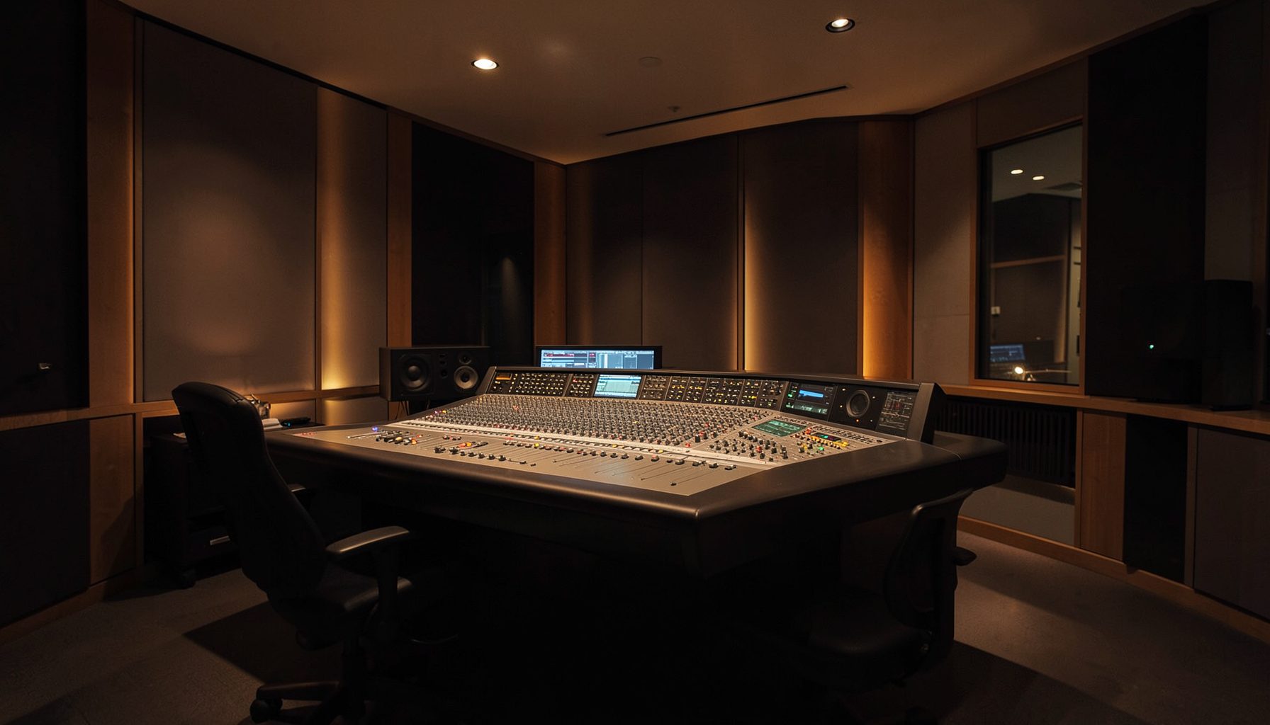
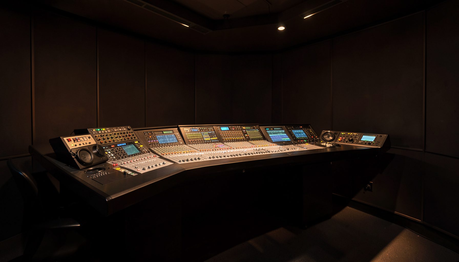
An on-air light is a small but important part of a radio studio. It tells presenters, producers, visitors and technical staff whether a microphone or studio feed is live. With Power Core, GPIO logic can connect that visual indicator to the wider broadcast workflow, allowing the lamp, tally, console state and automation system to respond consistently.
For Australian broadcasters, this is especially useful across busy metropolitan studios in Sydney, Melbourne and Brisbane, as well as regional stations where one room may handle breakfast, drive-time, news inserts and local production. A properly designed control path reduces accidental illumination, prevents confusing indications and gives presenters a clear status signal at a glance.
How GPIO Connects the Studio
GPIO means general-purpose input/output. In a broadcast environment, a Power Core node can use digital inputs to receive a state from a mixing console, wall panel, microphone switch or other control device. Digital outputs can then drive an interface connected to an external on-air lamp or tally system.
The lamp itself is usually not powered directly from the audio node. Instead, the output controls a suitable relay, contact closure interface, LED driver or professionally installed GPIO-to-light interface. This separation protects the networked audio equipment and allows the studio light to use the voltage and current requirements specified by its manufacturer.
Logic States And Switching Behaviour
A basic configuration might illuminate the sign whenever a presenter microphone is open. More advanced logic can combine several conditions: a microphone must be live, the studio must be selected for transmission, and an inhibit state must not be active. This prevents a local production microphone from triggering the main “ON AIR” indicator when it is not routed to the programme output.
Logic polarity is also important. Some external devices consider a closed contact to mean “on”, while others expect a high digital state. Power Core GPIO configuration should therefore match the interface documentation, with input inversion or output inversion applied where necessary. A short delay, debounce period or latching rule can also stop a light flickering when a fader is moved quickly.
Designing Clear Tally Rules
A good tally design begins by defining what the light actually means. “Microphone open” is different from “programme feed live”. In a two-studio facility, the main studio lamp may follow the transmission mix, while a smaller local indicator follows only the presenter’s own microphone. These distinctions should be documented before wiring or programming starts.
The logic can also include a warning state. For example, a red lamp may indicate transmission, while an amber indicator shows that a studio microphone is open but not currently routed to air. This gives operators useful information without relying on a single ambiguous signal.
Coordinating Power Core And VisTool
VisTool can provide a visual control layer for GPIO states, source selection and studio functions. A touchscreen button might trigger a controlled sequence that changes the console state, activates a tally and updates the operator display. For stations seeking consistent start-up behaviour, one-click studio presets can help bring related actions together rather than leaving the operator to perform them individually.
This approach is valuable when a studio is used by casual presenters, volunteers or rotating production teams. The interface should show the actual state returned by the system, not merely the last command pressed. If a lamp fails to respond or a route changes elsewhere, the screen should make that discrepancy visible.
Building Safe External Light Interfaces
Australian studios commonly operate on 230–240 V mains power, and an illuminated sign may involve mains wiring even when its control signal is low voltage. Any mains connection, relay cabinet or permanent electrical alteration should be specified and installed by an appropriately licensed electrician. The broadcast GPIO output should remain isolated from hazardous voltages through a suitable approved interface.
The practical details also matter: cable labelling, strain relief, ventilation, relay ratings and access for service. A Sydney commercial facility may use a compact LED tally beside a console, while a regional Queensland station might have a larger sign visible through a studio window. Both require the same disciplined separation between control logic and electrical load.
Managing Multiple Studios And Modes
Power Core’s networked architecture makes it possible to apply consistent GPIO behaviour across several rooms, but each room still needs clearly defined ownership of the on-air indication. A Melbourne broadcaster may have a main studio, news booth and production room sharing resources, while a community station may combine these functions during quieter periods.
Centralised control can help operators supervise the system, provided permissions and fallback behaviour are planned. Lawo’s discussion of a home management platform provides useful context for managing Power Core nodes and their surrounding operational environment. Local control should remain available for essential actions if a network connection or central panel becomes unavailable.
Testing, Maintenance And Documentation
Every on-air light should be tested under normal, abnormal and recovery conditions. Check what happens when a microphone is opened, closed, disconnected, rerouted or rapidly switched. Test a node restart, a network interruption and a failed lamp separately. The desired result should be documented, including whether the light remains on, turns off or enters a defined fault state.
Documentation can be as practical as a laminated signal map beside the rack: input source, logic rule, output contact, interface type and lamp location. This kind of process discipline resembles effective waste-stream management, where clear handling steps prevent confusion and avoidable loss; the principles described in livestock waste practices offer an unexpected but useful reminder that reliable operations depend on defined responsibilities and repeatable routines.
Power Core GPIO logic becomes most valuable when it reflects real studio states rather than a simple switch. Define the meaning of each indicator, isolate the external electrical load, verify polarity and timing, and make the status visible in both the studio and control interface. The key point is that an on-air light should be a trustworthy reflection of the broadcast path, not merely a lamp that happens to turn on.