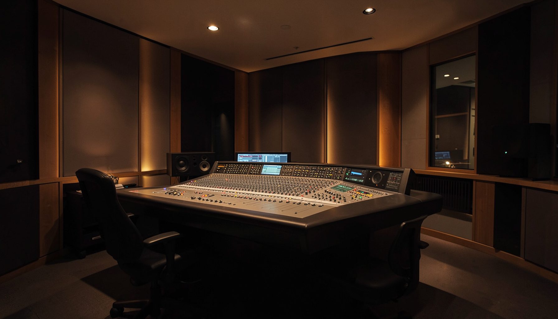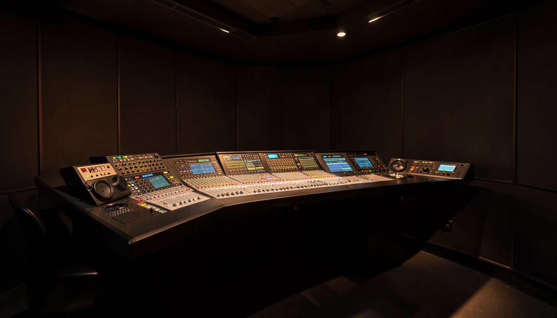
Planning Power Core Node Placement Across Multiple Storeys
A multi-storey broadcast facility needs more than a convenient rack location. Power Core nodes carry audio processing close to the studios, control rooms, and technical areas that depend on them, so their position affects cable lengths, network resilience, troubleshooting time, and future expansion.
The best design treats the building as a distributed audio system rather than a stack of isolated floors. Studio clusters, production rooms, newsroom spaces, and performance areas should each have a clear relationship with the node layer and the IP network connecting it.
Australian sites add practical constraints. A Sydney high-rise may have long vertical risers and strict landlord access rules, while a regional Queensland facility may need extra attention to cooling and humidity. Planning these details early helps avoid an expensive “she’ll be right” fix after installation.
| Placement approach | Strengths | Watch points | Suitable use |
|---|---|---|---|
| Central equipment room | Simple administration and monitoring | Longer analogue and network cable runs | Compact buildings |
| One node room per floor | Short local connections and easy expansion | More racks, power, and environmental controls | Large studio floors |
| Distributed nodes near studio clusters | Efficient signal paths and lower patching complexity | Requires disciplined network design | Multi-room radio facilities |
| Dual-node resilient layout | Better service continuity during failures | Higher capital and configuration demands | Main broadcast operations |
Map The Building Before Choosing Rack Locations
Start with an accurate floor plan showing studios, voice booths, edit suites, announcer positions, control rooms, transmission areas, and likely future spaces. Mark the vertical risers, cable trays, fire-rated penetrations, lift cores, plant rooms, and restricted areas. The shortest route on a drawing may be unusable once fire separation and building services are considered.
Measure the distance from each Power Core node candidate to the connected equipment, not just the distance between floors. A node placed beside a studio cluster can reduce copper runs, simplify tie-lines, and make local fault finding faster. In a Melbourne facility with studios spread across several levels, a floor-by-floor signal map may reveal that two smaller node locations are more practical than one central rack.
Match Node Density To Audio Workflows
Node density should follow how audio is created and shared. A primary radio studio with microphones, monitor feeds, mix-minus paths, codecs, and contribution sources may need a much closer processing resource than a lightly used edit room. Group rooms by workflow, then identify which signals must remain local and which should travel over the IP network.
Lawo Power Core nodes can support a networked architecture where processing and routing are distributed rather than tied to a single console position. That makes it possible to place resources near high-use areas while retaining central control. A node serving a newsroom cluster, for example, can handle local sources while remaining available to Ruby surfaces and other connected production positions.
Protect Network Paths And Timing
Every node location needs a network design that supports predictable timing, bandwidth, and redundancy. Use diverse cable routes where practical: a primary path through one riser and a secondary path through another is stronger than two cables bundled through the same congested shaft. Document switch locations, fibre paths, patch panels, and port assignments before racks are delivered.
Clocking and packet timing deserve the same attention as physical distance. Confirm that the selected switches, VLAN structure, multicast handling, and timing distribution suit the complete audio system. In Australia, long procurement cycles can make replacement hardware difficult to source quickly, so approved switch models and spare strategies should be agreed with the integrator early.
Account For Power, Cooling, And Access
A technically ideal node room is still a poor choice if it overheats or cannot be serviced during a live shift. Check rack heat loads, dedicated circuits, UPS capacity, ventilation, dust control, and generator-backed power. Brisbane and Darwin sites may need particularly careful cooling design, while older buildings in Adelaide or Perth may have limited electrical capacity on upper floors.
Leave working clearance around racks and provide a practical route for removing equipment. A node hidden behind a permanently fixed cabinet can turn a minor fault into an all-day outage. Keep doors, loading paths, and lift dimensions in the design, and coordinate with local electricians, cablers, and building managers before the fit-out begins.
Design For Resilience Where It Matters Most
Not every floor needs duplicate hardware, but core broadcast paths usually deserve a higher level of protection. Consider paired network routes, separate power feeds, UPS-backed equipment, and a second Power Core node for the most critical studios or control positions. Resilience should be based on the operational impact of failure rather than applied uniformly to every room.
A useful test is to ask what happens if one node, switch, riser, or equipment room becomes unavailable during breakfast radio or a major outside broadcast. If the answer involves manual repatching under pressure, revise the architecture. Sydney and Melbourne stations often have dense schedules and limited engineering cover overnight, making remote diagnostics and graceful failover especially valuable.
Keep Control And Monitoring Practical
Node placement should support the people who operate and maintain the system. Central monitoring can provide an overall view, but engineers still need sensible physical access to patch panels, status indicators, and network equipment. Label every rack, fibre, copper bundle, power feed, and logical connection using a naming convention that works across floors.
For visual control and configuration, VisTool software can form part of a clear operational layer around the distributed system. Screens should reflect real workflows: studio source selection, monitor control, route status, alarms, and emergency paths. Avoid building pages that expose every technical parameter to every operator; role-based views reduce mistakes during a busy bulletin or live crossing.
Validate The Layout Before Installation
A scaled drawing and a signal-flow review should precede final rack orders. Test ordinary and exceptional cases: a studio moved to another floor, an extra codec added, a remote contribution feed arriving, or a node needing replacement. Include the actual cable tray capacity and spare fibre count, not an optimistic allowance.
Run a commissioning plan that checks latency, clock stability, failover, multicast behaviour, GPIO or control integration, and audio quality at every endpoint. For a regional station or a university facility, leave enough spare ports and rack units for likely growth rather than designing only for day one. A short site walk with the broadcast engineer, IT team, electrical contractor, and cabling tradie can expose problems while they are still cheap to fix.
Make Expansion Part Of The First Design
A well-placed Power Core node should serve current rooms without blocking tomorrow’s changes. Reserve rack units, switch capacity, power headroom, and cable pathways for additional studios, podcast rooms, streaming services, or theatre and live-production work. Broadcast 3.0-style systems gain value when facilities can add software-defined workflows without rebuilding the physical backbone.
The practical test is simple: each important room should have a short, documented path to suitable processing, at least two credible network routes where continuity matters, and enough environmental and physical capacity for expansion. Put the nodes where audio work happens, protect the paths that connect them, and verify the design against real building conditions before the first rack is installed.