Designing a Studio-to-Transmitter Link with Lawo AoIP and Microwave Bridges
A reliable studio-to-transmitter link (STL) now needs to carry more than a stereo programme feed. Radio teams expect clean audio, remote contribution, metadata, talkback, monitoring and control to travel across the same operational fabric. Lawo’s Audio-over-IP approach combines networked processing with flexible studio and transmission workflows, making it suitable for metropolitan stations and widely dispersed Australian sites.
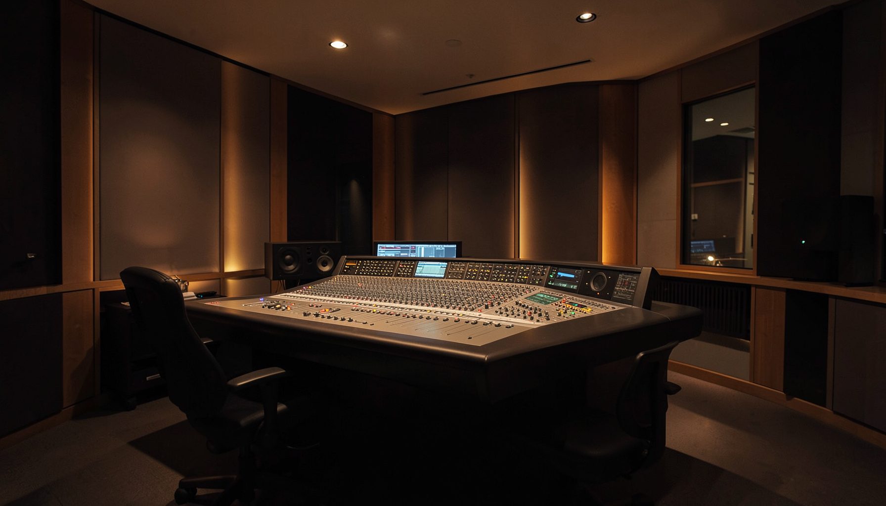
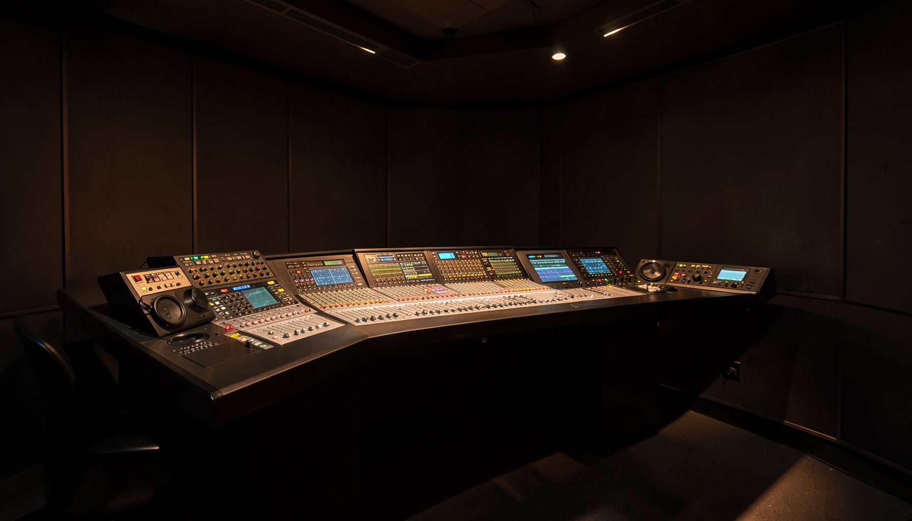
The design challenge is to connect the studio, transmitter site and any backup path without creating a fragile chain of point-to-point devices. A Lawo Ruby console, Power Core audio node, VisTool interface and RƎLAY virtual tools can work together across a managed AoIP network, while a licensed microwave bridge provides a dedicated path where fibre is unavailable or operational independence matters.
Map The End-To-End Signal Path
Begin by defining every source and destination: microphones, playout, automation, codecs, studio monitors, transmitter processors, confidence returns and emergency audio. In a typical setup, Ruby handles operator control, Power Core provides centralised I/O and DSP, and the STL carries the programme mix plus selected ancillary channels.
Keep the main programme path separate from optional services. A stereo or multichannel feed may be the transmission priority, while return audio, GPIO, RDS or DAB metadata, intercom and engineering access can use reserved streams. This makes fault-finding faster when a transmitter site reports silence during a busy arvo shift.
Build The AoIP Core
Use RAVENNA and AES67-compatible networking to establish interoperable audio transport between Lawo devices and approved third-party equipment. Power Core can act as a powerful networked audio engine, reducing the need for large local racks at every studio position. VisTool gives operators and engineers a practical interface for routing, monitoring and system control.
The Ethernet design should include managed switches, redundant uplinks, separate control and media traffic where appropriate, and carefully planned multicast behaviour. IGMP snooping, queriers and QoS policies are essential rather than optional. A poorly configured switch can make an otherwise excellent audio system appear unreliable, particularly when several studios share one campus network.
Select The Microwave Bridge
A microwave bridge is valuable when the transmitter is across town, beyond a difficult road corridor or in a regional location where leased fibre is expensive. The radio link should be engineered for clear line of sight, sufficient fade margin and the required channel bandwidth. Rooftop obstructions in Sydney, rising terrain around Brisbane or long rural paths in Western Australia each demand different surveys.
Choose equipment that can transport the required AoIP payload transparently, or place a small gateway at each end to convert between network and radio transport. The bridge should support traffic prioritisation, VLAN handling and comprehensive statistics. In Australia, frequency coordination and licensing must be addressed with the ACMA, and the design should account for heat, dust, storms and difficult access at remote transmitter compounds.
Protect Timing And Audio Quality
Networked audio depends on stable timing. Use a resilient PTP design with a defined grandmaster strategy, suitable boundary or transparent clocks, and a holdover plan for loss of reference. The microwave section must preserve timing performance or provide a controlled timing boundary that does not cause audible interruptions.
Set packet delay and jitter buffers according to the path rather than choosing arbitrary values. A short buffer can reduce latency for live presentation, but a longer one may be appropriate on a variable wireless route. Monitor packet loss, late packets, clock status and stream subscription state so that engineers can identify whether a fault is in the console, switch, bridge or transmitter input.
Add Control And Virtual Workflows
An STL becomes more useful when it carries operational control as well as audio. RƎLAY can support virtualised radio production and contribution workflows, while AutoMix can assist with consistent speech and music handling in suitable formats. Ruby remains the operator-facing control surface, with Power Core handling much of the processing behind it.
VisTool can present simplified pages for local staff and detailed engineering views for the network operations team. Access rights should distinguish presenters, producers and technical users. That matters for a group with studios in Melbourne, Perth and regional New South Wales, where a small local team may need immediate recovery tools without being able to alter the entire station’s routing.
Engineer Resilience And Recovery
Use diverse paths wherever the transmitter is mission-critical. The primary microwave hop might be paired with fibre, a managed IP service or a compressed backup codec over another carrier. Automatic changeover should be tested with real programme audio, including the return path and any silence-detection logic.
Document bypass routes and keep a local emergency source at the transmitter. A scheduled test can verify power systems, antenna alignment, bridge failover, PTP recovery and transmitter input selection before bushfire smoke, flooding or a carrier outage exposes a weakness. When reviewing total operating cost, broader comparisons such as this operational cost context can also reinforce the need to measure ongoing maintenance, not just initial equipment prices.
Commission For Australian Conditions
Acceptance testing should measure end-to-end delay, audio loudness, failover time, packet loss tolerance and recovery after a power interruption. Test at the busiest expected network load, not only with an idle switch and one audio stream. Include the transmitter shelter, studio control room and any remote contribution points in the same test record.
Operational governance matters as much as technical performance. Keep configuration backups, frequency documentation, bridge passwords and routing diagrams in a controlled system. For sites serving large distances across the outback, arrange spares and remote-hands support before installation. A licensing and compliance review, similar in spirit to the practical checks described in this licensing case, helps ensure the technical design can be operated lawfully and consistently.
| Design area | Recommended approach | Main Australian consideration |
|---|---|---|
| Studio core | Ruby, Power Core and managed RAVENNA/AES67 networking | Shared-campus congestion and multicast control |
| Wireless STL | Licensed microwave bridge with QoS and monitoring | ACMA coordination, line of sight, heat and storms |
| Timing | Redundant PTP grandmaster and documented holdover | Stable operation across long or remote paths |
| Resilience | Diverse fibre, IP or codec backup | Bushfire, flooding and carrier outages |
| Operations | VisTool dashboards, alarms and configuration backups | Limited engineering access at regional sites |
A strong studio-to-transmitter design treats AoIP, microwave, timing, control and recovery as one system. Keep the main audio path simple, give every network service a defined priority, and verify the complete chain under realistic conditions. For most Australian broadcasters, the practical baseline is a managed Lawo AoIP core, a properly licensed microwave bridge, independent backup connectivity and documented failover that an engineer can test before the next transmission shift.